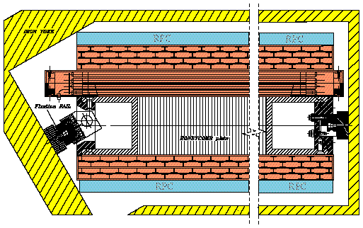
Figure 2: Cross section of a barrel muon chamber.
2 Central Muon Detector
The concept of the construction of a redundant detector was
propagated through all the design phases. In fact the basic
barrel chamber module is composed by three superlayers ( two
measuring the coordinate in the bending plane and one in the
longitudinal plane) each one split in four layers of staggered
drift tubes as shown in Figure 2.
Figure 2: Cross section of a barrel muon chamber.
The inner superlayer in the bending plane is separated from
the other ones by a 20cm thick aluminium honeycomb plate that
supplies the module with the required stiffness, permits the
opening of an electromagnetic shower eventually generated inside
the iron allowing a better measurement in the superlayers away
from the iron and provides a lever arm in the bending plane
useful for triggering purposes.
The barrel chambers were supposed to be drift chambers and were
required to provide a final resolution of 100µm per station and
to be linear in the time to space conversion, i.e. to have a
drift velocity constant along the whole drift path.
Most of the past studies were therefore devoted to careful
evaluation of the drift cell layout in order to meet these
requirements. The final result was a multi-electrode cell built
glueing insulated aluminium I-beams on grounded aluminium plates
carrying one shaping electrode facing the anode wire. The cell
layout is shown in Figure 3, where the electron drift lines as
computed from the simulation program GARFIELD [2] are also shown.
The shaping effect of the electrode facing the anode and of the
C-shape of the cathode is evident, since all the drift field
lines are swept to the cathode.
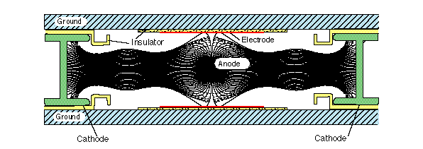
Figure 3: Drift cell layout showing drift lines.
Several tests were done on a muon beam using various chamber
prototype and different gas mixtures [3]. The results of the
tests fully matched the requirements. Figure 4 shows that the
deviation from linearity of the space-time relationship was below
100 µm all along the drift cell while Figures 5a and 5b show
that also the single hit resolution is reasonably flat, even for
large angles. The resolution averaged on the drift cell is
reported in Figure 5c, where we see that the target resolution of
100 µm per eight planes is achieved for the whole expected
angular range, since we do not expect angles of incidence larger
than 45.
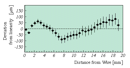
Figure 4: Deviation from linearity along drift cell for normal
incident muons.
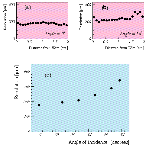
Figure 5: Performance of the drift cell: resolution along drift
cell (a) at normal incidence; (b) at large angle ; (c) resolution
versus incident angle.