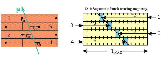
Figure 13: Exemplification of the generalized meantimer method.
5.2.1 Barrel Detector Algorithm
We have seen that the drift chambers are composed of
Superlayers made of groups of four staggered layers of drift
tubes packed together. This design assures the redundancy needed
in the detector, but it was also chosen on purpose to allow the
parent bunch crossing identification in the trigger.
Infact bunch crossing is detected using a generalized mean-timer
method. Its principle is shown in Figure 13.

Figure 13: Exemplification of the generalized meantimer method.
The sketch on the left-hand side shows a particle crossing a
group of four tubes and generating four drift times. The one on
the right-hand side shows a group of four shift registers each
one associated to a drift cell. The signals generated in each
cell are shifted in the register: the four hits are aligned
always at a fixed time TMAX, equal to the maximum drift time in
the cell, after the muon crossing time, thus uniquely identifying
the parent bunch crossing. The track inclination and the crossing
position can be determined by the shift times ts = TMAX - td
giving a rough track measurement.
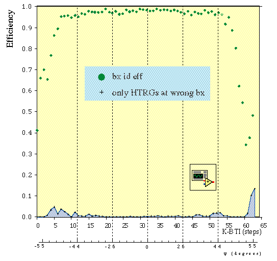
The actual algorithm is described elsewhere[6] and ASIC
prototypes were recently produced and tested. The bunch crossing
tagging efficiency measured using the prototypes is shown in
Figure 14 as a function of the incident angle for a sample of
drift times patterns provided generating single muons inside the
detector with full background simulation.

Figure 14: Bunch crossing detection efficiency for a set of ASICs
recently tested. The abscissa scale is not linear.